TM 9-2350-261-34
I N S T A LL
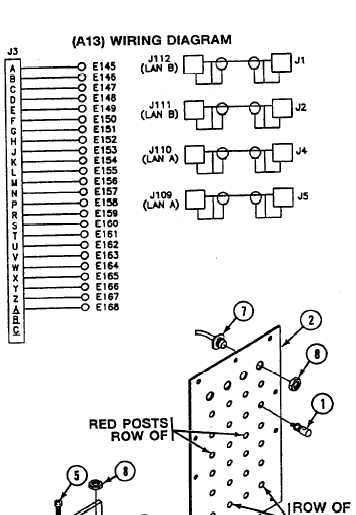
NOTE
See wiring diagram
for
assem-
ble/disassemble of wires to connec-
tors/binding posts.
Follow
illustration
for assem-
ble/disasemble of red/black binding posts.
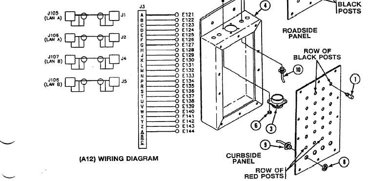
8. Install 24 binding posts (1) on faceplate (2).
9. Install connector J1 (3) on box (4) and
secure with four screws (5) and new
lockuuts (6).
NOTE
Do step 10 for roadside data panel only.
Do step 11 for curbside data panel only.
10. Install four connectors J109 thru J112 (7),
on faceplate (2) and secure with
jamnuts (8).
11. Install four connectors J105 thru J108 (9)
on faceplate (2) and secure with
jamnuts (8).
12. Install four connectors J1, J2, J4, J5 (10),
on box (4) and secure with jamnuts (8).
GO TO NEXT PAGE
Change 4
21.1-21