TM 9-2350-261-34
NOTE
Tag all leads before removal for proper
installation later.
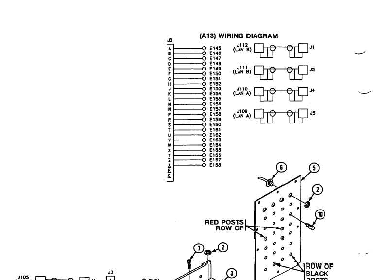
Follow illustration for remove/install of
red/black binding posts.
See wiring diagram for disassem-
ble/assemble of wires to connec-
tors/binding posts.
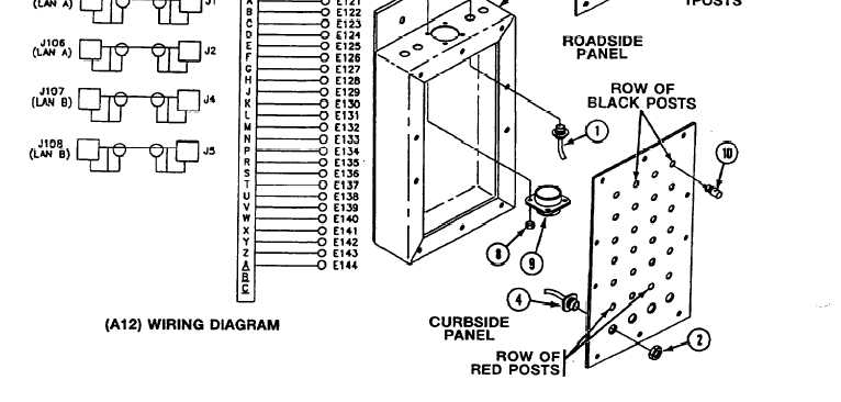
3. Remove four connectors J1, J2, J4, J5 (1),
and jamnuts (2) from box (3).
NOTE
Do step 4 for curbside data panel only.
Do step 5 for roadside data panel only.
4. Remove four connectors J105 thru J108 (4)
and jamnuts (2) from faceplate (5).
5. Remove four connectors J109 thru J112 (6)
and jamnuts (2) from faceplate (5).
6. Remove four screw (7), locknuts (8), and
connector J1 (9) from box (3). Discard
locknuts.
7. Remove 24 binding posts (10) from
faceplate (5).
21.1-20
Change 4