TM 9-2350-261-34
A S S E M B L E
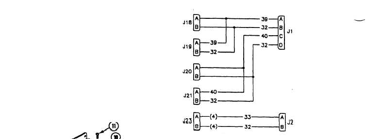
11. Connect leads to connectors if necessary.
NOTE
S e e w i r i n g d i a g r a m f o r a s s e m -
ble/disassemble of wires to connectors.
7. Install connector J23 (1) on cover (2) with
dustcap (3), secure with four screws (4) and
new locknuts (5).
8. Install four connectors J18-J21 (6) on cover
(2) with dust caps (3), secure with sixteen
screws (7) and new locknuts (8).
9. Install connector J2 (9) on extension box
(10), secure with four screws (11) and new
locknuts (12).
10. Install connector J1 (13) on extension
box (10), secure with four screws (14) and
new locknuts (15).
12. Install cover (2) on extension box (10) with
gasket (16) and secure with four
screws (17).
FOLLOW-THROUGH STEPS
1. Install roadside DC power extension box
(see your -20).
END OF TASK
21.1-18
Change 4