TM 9-2350-261-20-2
R E P L A C E P I V O T S T E E R H A N D L E S A N D L I N KS
DESCRIPTION
This task covers:
Remove (page 23-62).
Clean, Inspect, and Replace (page 23-63).
Install (page 23-63).
INITIAL SETUP
Tools:
References:
General Mechanics Tool Kit (Item 30, App D)
See your -10
Materials/Parts:
Equipment Conditions:
Cotter pin (4)
Engine stopped/shutdown (see your -10)
Self-locking nut (4)
Carrier blocked (see your -10)
Driver’s seat removed (page 24-127)
Personnel Required:
Unit Mechanic
REMOVE
3.
1.
2.
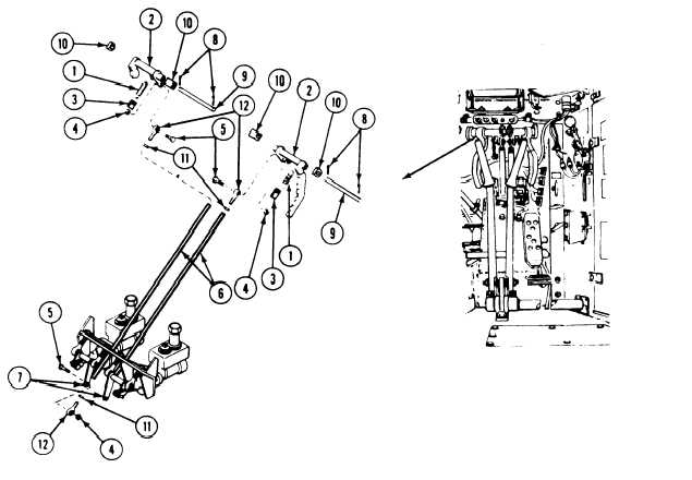
Disconnect two springs (1) from two control
handles (2) and brackets (3).
4.
Remove four locknuts (4), screws (5), and two
links (6) from two bellcranks (7) and control
handles (2). Discard locknuts.
Remove four cotter pins (8), two shafts (9),
and two control handles (2)
(10). Discard cotter pins.
Remove four nuts (11) and
(12) from two links (6).
from four mounts
rod end bearings
23-62