TM 9-2350-261-20-2
B L E E D P I V O T S T E E R S Y S T EM
INITIAL SETUP
Tools:
References:
General Mechanics Tool Kit (Item 30, App D)
See your -10
See your LO
Materials/Parts:
FRH hydraulic fluid (Item 19, App C)
Equipment Conditions:
Personnel Required:
Unit Mechanic
Helper (H)
Engine stopped/shutdown (see your -10)
Ramp lowered (see your -10)
Carrier blocked (see your -10)
Trim vane lowered and power plant front
access door open (see your -10)
BLEED
1.
2.
3.
4.
5.
6.
N O T E
Bleed one side of system (two caliper
halves) at a time. Keep master cylinder
full during bleeding.
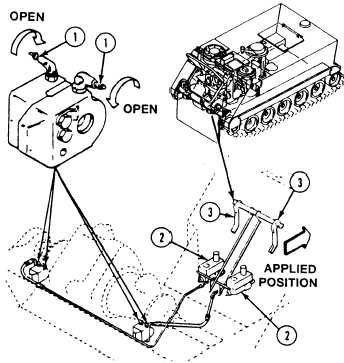
Attach a short hose and container to bleeder
valves (1) (one valve at a time).
Remove master cylinder cap (2). Fill cylinder
with FRH hydraulic fluid (see your -10).
Open bleeder valves (1).
Move handle (3) until fluid coming out of
bleeder valves (1) is free of air.
Hold handle (3) back in applied position (as
shown) and close bleeder valves (1).
After bleeding, add FRH hydraulic fluid only
as needed. Fluid level should be within
1/2-3/4-in (13-19mm) from top of cylinder.
Do not overfill (see your LO).
Pull control handle to applied position and hold
it there. If handle continues to move after ap-
plied position is reached, master cylinder, hose,
tube, or connection is bad. Repair or replace bad
parts (page 23-66).
FOLLOW-THROUGH STEPS
1. Close power plant front access door and raise
3. Operate carrier (see your -10). Check that
trim vane (see your -10).
pivot steer system operates properly.
2. Raise and lock ramp (see your –10).
4. Stop/shutdown engine (see your –10).
END OF TASK
23-61