TM 9-2350-261-20-2
8.
9.
10.
11.
12.
13.
14.
15.
If removed,
in ramp.
If removed,
bulkhead.
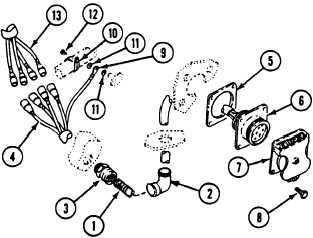
install spring (1)
install connector
Route leads (4) through new
out through elbow (2).
Install gasket (5), receptacle
and elbow (2)
(3) in rear
gasket (5), and
(6), and cover
(7) on ramp. Secure with four screws (8).
Route lead (4) through spring (1) and con-
nector (3).
Install circuit 90 lead (9) between clamp
(10) and weldnut on hull. Secure with two
new lockwashers (11) and screw (12).
Install shell connectors on leads (4)
(page 14-9).
Connect leads (4) to leads (13).
FOLLOW-THROUGH STEPS
1. Install rear floor plates (page 24-37).
3.
2. Connect battery ground leads (page 13-2).
4.
Turn MASTER SWITCH/BATTERY SWITCH
ON (see your -10). Check with multimeter to
make sure harness is installed properly.
Turn MASTER SWITCH/BATTERY SWITCH
OFF (see your -10).
END OF TASK
17-3
INSTALL