TM 9-2350-261-20-2
R E P L A C E L E A D A S S E M B L Y , U T I L I T Y O U T L ET
( M 5 7 7 A 2 A N D M 1 0 6 8 O N L Y)
INITIAL SETUP
Tools:
References:
General Mechanics Tool Kit (Item 30, App D)
see your -10
Digital Multimeter (Item 43, App D)
Equipment Conditions:
Personnel Required:
Engine stopped/shutdown (see your -10)
Unit Mechanic
Battery ground leads disconnected (page 13-2)
REMOVE
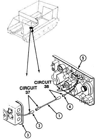
1. Disconnect lead assembly (1) from circuit 37
lead (2) at master switch panel (3).
2. Disconnect lead assembly (1) from circuit 38
lead (4) at instrument panel (5). Remove lead
assembly.
CLEAN, INSPECT,
3. Check lead continuity
Replace bad lead.
AND REPLACE
Use digital multimeter.
4. Check connectors. Replace cracked or broken
connectors (page 14-1).
INSTALL
N O T E
Lead assembly (1) is banded as circuit 37
at master switch panel and circuit 38 at
instrument panel. Make sure it is
installed properly.
5. Connect
lead (4)
lead assembly (1) to circuit 38
at instrument panel (5).
lead assembly (1) to circuit 37
at master switch panel (3).
6. Connect
lead (2)
FOLLOW-THROUGH STEPS
1. Connect battery ground leads (page 13-2).
2. Turn MASTER SWITCH ON to check that
lead assembly is installed properly. Turn
MASTER SWITCH OFF (see your -10).
END OF TASK
Change 3
17-7