TM 9-2350-261-20-2
R E P L A C E E N G I N E C O O L A N T T E M P E R A T U R E S W I T CH
INITIAL SETUP
Tools:
References:
General Mechanics Tool Kit (Item 28, App D)
See your -10
Materials/Parts:
Equipment Conditions:
Sealing compound (Item 54, App C)
Engine stopped/shutdown (see your -10)
Carrier blocked (see your -10)
Personnel Require:
Trim vane lowered and power plant front
Unit Mechanic
access door open (see your –10)
Coolant level drained to below thermostat
housing (page 8-3)
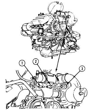
REMOVE
1. Disconnect circuit 33 lead (1) from engine
coolant temperature switch (2).
2. Remove switch (2) from thermostat hous-
ing (3).
INSTALL
3. Coat threads of switch (2) with sealing
compound.
4.
5.
Install switch (2) in thermostat housing (3).
Connect circuit 33 lead (1) to switch (2).
FOLLOW-THROUGH STEPS
1. Refill cooling system (page 8-5).
3. Stop/shutdown engine (see your -10).
2. Start engine (see your -10). Check for coolant
4. Close power plant front access door, and raise
leaks at engine coolant temperature switch
trim vane (see your -10).
(page 3-144).
END OF TASK
15-3