TM 9-2350-261-20-2
R E P L A C E E N G I N E L O W O I L P R E S S U R E S W I T C H
INITIAL SETUP
Tools:
References:
General Mechanics Tool Kit (Item 30, App D)
See your -10
Materials/Parts:
Equipment Conditions:
Sealing compound (Item 46, App C)
Engine stopped/shutdown (see your -10)
Carrier blocked (see your -10)
Personnel Required:
Battery ground lead disconnected (13-2)
Unit Mechanic
Trim vane lowered and power plant front
access door open (see your –10)
REMOVE
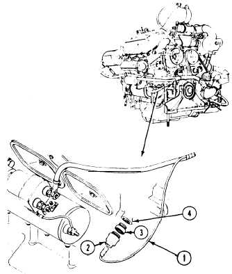
1. Disconnect circuit 34 lead (1) from oil pres-
sure switch (2).
2. Remove switch (2) from bushing (3).
3. If needed, remove bushing (3) from engine
block (4) .
INSTALL
4. If removed, coat threads of bushing (3) with
sealing compound.
5. Install bushing (3) in engine block (4).
6. Install switch (2) in bushing (3).
7. Connect circuit 34 lead (1) to switch (2).
FOLLOW-THROUGH STEPS
1.
2.
Connect battery ground lead (page 13-2).
3.
Turn MASTER SWITCH ON and observe low
oil pressure warning light. Light should go
ON (see your -10.
4.
5.
Start engine and check for oil leaks at engine
low oil pressure switch. Low oil pressure
warning light should go out after engine is
started. Stop engine (see your -10).
Turn MASTER SWITCH OFF (see your –10).
Close power plant front access door, and raise
trim vane (see your –10).
END OF TASK
15-2