TM 9-2350-261-20-2
R E P L A C E D I F F E R E N T I A L S W I T C H L E AD
INITIAL SETUP
Tools:
References:
General Mechanics Tool Kit (Item 30, App D)
See your -10
Materials/Parts:
Equipment Conditions:
Self–locking nut
Engine stopped/shutdown (see your -10)
Trim vane lowered and power plant front
Personnel Required:
access door open (see your -10)
Unit Mechanic
1.
2.
3.
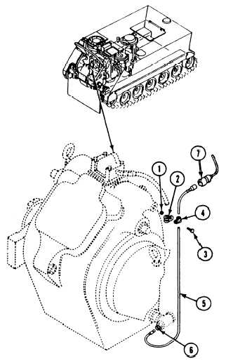
Remove locknut (1), clamp (2), and screw (3)
from clamp (4). Discard locknut.
Disconnect circuit 328 lead (5) from differen-
tial high oil temperature switch (6) and
power plant wiring harness (7). Remove lead.
If replacing lead (5), remove clamp (2) from
l e a d .
INSTALL
4.
5.
6.
If removed, install clamp (2) on lead (5).
Route lead (5) along differential and connect
lead to power plant wiring harness (7) and
switch (6).
Place clamp (2) on clamp (4). Secure with
screw (3) and new locknut (1).
FOLLOW-THROUGH STEPS
1. Close power plant front access door and raise
trim vane (see your -10).
END OF TASK
15-5
REMOVE