TM 9-2350-261-20-2
5.
6.
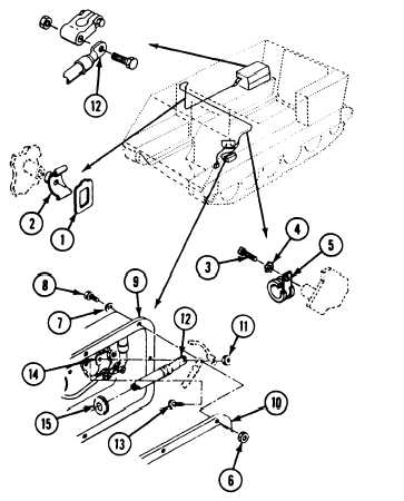
On M106A2 and M125A2 carriers, remove
one clip (1) from cradle (2). Remove two
SCrewS (3), washers (4), and clamps (5)
from two hull weldnuts.
Remove eight nuts (6), washers (7), screws
(8), and master switch panel (9) from
distribution box (10).
NOTE
Nut (11) and screw (13) secure three
leads circuits 2, 6, and 400, to the master
switch bus bar, on all carriers covered by
this task except M741A1. On M741A1
carriers the nut and screw secure two
leads, circuits 6 and 400, to the bus bar.
7.
8.
Remove nut (11), lead (12), and screw (13)
from master switch bus bar (14). Remove
lead and grommet (15) from panel (9).
Discard grommet.
Pull lead (12) from hull support channel. Re-
move lead from carrier. --
WARNING
Battery posts and cables
touched by metal objects
can short circuit and bum
you. Do not wear jewelry,
necklaces, or watches when
working on the electrical
system. Keep tools away from posts,
wires, and terminals.
CAUTION
Do not start vehicles while batteries are
disconnected.
S t a r t i n g e n g i n e w i th
outside power will damage electrical
components in the regulator.
CLEAN, INSPECT, AND REPAIR
9. Clean lead terminals and mating surfaces
with terminal cleaner.
10. Check leads. Replace worn leads and dam-
aged connectors (page 14-3).
INSTALL
11. Route circuit 6 lead (12) through hull sup-
port channel.
12. Install new grommet (15) on lead (12). In-
stall lead and grommet in master switch
panel (9).
NOTE
Nut (11) and screw (13) secure three
leads, circuits 2,6, and 400, to the master
switch bus bar on all earners except
M741A1. On M741Al carrier the nut and
screw secure two leads, 6 and 400. Be sure
you secure all leads to the master switch
bus bar when you install the screw (13)
and nut (11).
13. Place lead (12) on master switch bus bar
(14). Secure with screw (13) and nut (11).
14. Place panel (9) on distribution box (10). Se-
cure with eight washers (7), screws (8), and
nuts (6).
13-14


