TM 9-2350-261-20-2
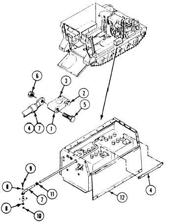
10. Place terminal lug (1) on battery post. Se-
cure with screw (2) and nut (3).
11. Place jumper lead (4) on two screws (5) of
two terminal lugs (1). Secure with two
nuts (6).
12. Install circuit 7 lead (7) as follows:
a. Place lead (7) on hull mount. Secure
with two washers (8), screw (9), and
nut (10).
b. Install new grommet (11) in battery box
(12). Route lead (7) through grommet
into battery box.
c. Place lead (7) on screw (5) of terminal
adapter (1) and secure with nut (6).
13. Coat tops of four battery terminal lugs with
grease.
FOLLOW-THROUGH STEPS
1. Install battery access cover (page 13-6).
3. Start engine (see your -10).
2. Turn MASTER SWITCH ON. Check
4. Raise and lock ramp (see your -10).
BATT-GEN gage on instrument panel. Gage
should read in BATT green or yellow zone
5. Stop/shutdown engine (see your -10).
(see your –10).
.
END OF TASK
13-9