15.
16.
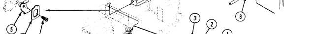
On M106A2 and M125A2 carriers, aline two 17.
clamps (1) with weldnuts. Secure with two
washers (2) and screws (3). Place lead (4)
in cradle (5). Secure with clip (6).
18.
on M113A2, M741A1, and M901A1 carri-
ers, install five cradles (5) on hull weldnuts.
TM 9-2350-261-20-2
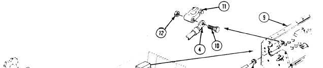
Install new grommet (8) on lead (4). Install
lead and grommet in battery box (9),
Install screw (10) and lead (4) on battery
terminal lug (11). Secure with nut (12).
Secure with five screws (7). Place lead (4)
in five cradles and secure with clips (6).
FOLLOW-THROUGH STEPS
1 Install battery box cover (page 13-3).
4. Raise and lock ramp (see your -10).
2. Connect battery ground lead (page 13-2).
5. Stop/shutdown engine (see your -10).
3. Turn MASTER SWITCH ON (see your -10).
Check that circuit 6 lead is installed correct-
ly. MASTER SWITCH light should come on.
END OF TASK
13-15