TM 9-2350-261-20-2
REPLACE STOP LIGHT SWITCH AND BRACKET
DESCRIPTION
This task covers:
Remove (page 12-132)
Install (page 12-132) .
Adjust (page 12-133).
INITIAL SETUP
Tools:
References:
General Mechanics Tool Kit (Item 30, App D)
See your -10
Materials/Parts:
Equipment Conditions:
Self-locking nut (2)
Engine stopped/shutdown (see your –10)
Battery ground lead disconnected (page 13-2)
Personnel Required:
Trim vane lowered and power plant front
Unit Mechanic
access door open (see your -10)
REMOVE
1.
‘2.
3.
4.
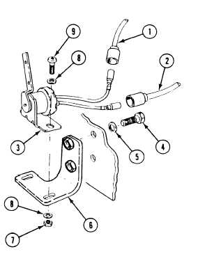
Disconnect circuit 75A lead (1) and circuit
75B lead (2) from switch (3).
From driver’s compartment, remove two
screws (4) and washers (5) from driver’s
bulkhead and bracket (6).
From power plant compartment, remove
bracket (6) with switch (3) attached.
Remove two locknuts (7), four washers (8),
two screws (9), and switch (3) from
bracket (6). Discard locknuts.
INSTALL
5.
6.
7.
Place switch (3) on bracket (6). Secure with
two screws (9), four washers (8), and two
new locknuts (7).
Align bracket (6), with switch (3) attached,
to driver’s compartment bulkhead. Secure
with two washers (5) and screws (4).
Connect circuit 75B lead (2) and circuit 75A
lead (1) to switch (3).
12-132