TM 9-2350-261-20-2
CLEAN, INSPECT, AND REPAIR
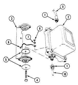
3. Check circuit lead connectors (1). Replace con-
nectors that have bent or missing contact
pins (page 14–1).
INSTALL
4. Install power supply (2) on two mounts (3).
Secure with four screws (4), eight washers
(5), ground lead (6), four new -
lockwashers (7), and nuts (8).
5. Connect circuit 517 lead (9) and
lead (10) to power supply (2).
circuit 516A
FOLLOW-THROUGH STEPS
1. Connect battery ground lead (page 13-2).
4.
2. Turn MASTER SWITCH ON (see your -10).
5.
3. Install and operate M19 periscope to check
that infrared power supply is operable
6.
(see your -10).
Turn all infrared periscope switches off
(see your -10).
Turn MASTER SWITCH OFF (see your -10).
Stow periscope (see your –10).
END OF TASK
Change 1
12-135