TM 9-2350-261-20-2
R E P L A C E R I G H T H E A D L I G H T W I R I N G H A R N E S S
D E S C R I P T I ON
This task covers:
Remove (page 12-79).
Clean, Inspect, and Repair (page 12-80).
Install (page 12-80).
INITIAL SETUP
Tools:
General Mechanics Tool Kit (Item 30, App D)
Digital Multimeter (Item 43, App D)
Electrical Tool Kit (Item 75, App D)
Materials/Parts:
Insulation tape (Item 26, App C)
Lockwasher (4)
Terminal (6)
Personnel Required:
Unit Mechanic
References:
See your -10
Equipment Conditions:
Engine stopped/shutdown (see your -10)
Carrier blocked (see your -10)
Trim vane lowered (see your -10)
Power plant front access door open
(see your -lo)
Power plant grill raised (page 5-2)
Battery ground lead disconnected (page 13-2)
R E M O VE
1.
2.
3.
4.
5.
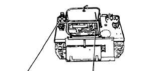
Disconnect right headlight wiring harness (1)
from front main wiring harness (2) at
driver’s compartment bulkhead.
Disconnect circuits 514 and 515 leads
(3 and 4) from right infrared headlight
Disconnect circuit 25 lead (6) from horn
Disconnect circuit 20 lead (8) from right
blackout marker light (9).
(5).
(7).
Disconnect circuits 17, and 18 leads
(10 and 11) from right service headlight (12).
GO TO NEXT PAGE
12-79