TM 9-2350-261-20-2
R E P L A C E R A M P D O O R S W I T C H A N D M O U N T
( M 5 7 7 A 2 A N D M 1 0 6 8 O N L Y)
D E S C R I P T I O N
This task covers: Remove (page 12-74).
Clean and Inspect (page 12-74).
Install (page 12-74). Adjust (page 12-75).
I N I T I A L S E T UP
Tools:
References
General Mechanics Tool Kit (Item 30, App D)
See your -10
Materials/Parts:
Equipment Conditions
Self-locking nut (4)
Engine stopped/shutdown (see your -10)
Self-locking nut
Battery ground lead disconnected (page 13-2)
Carrier blocked (see your -10)
Personnel Required:
Unit Mechanic
R E M O V E
1.
2.
3.
4.
5.
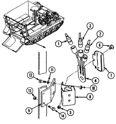
Disconnect circuit 38 lead (1), circuit 38B
lead (2), and circuit 38C lead (3) from
switch (4).
Remove locknut (5), screw (6), and retainer
(7) from actuator (8). Discard locknut.
Remove switch (4) from. actuator (8).
Remove two locknuts (10), washers (11),
screws (12), and actuator (8) from bracket
(9). Discard locknuts.
Remove two locknuts (13), screws (14), and
bracket (9) from hull. Discard locknuts.
C L E A N A N D I N S P E C T
6. Check for cracks or other damage to switch.
If damaged, replace switch.
N O T E
Steps 11 through 16 tell you how to adjust
s w i t c h b e f o r e t i g h t e n i n g n u t s at
installation procedure.
7. Place bracket (9) on hull. Secure with two
screws (14) and new locknuts (13).
8.
9.
10.
Place actuator (8) on bracket (9). Secure
with two screws (12), washers (11), and
new locknuts (10). Do not tighten screws.
Place switch (4) on actuator (8). Secure
with retainer (7), screw (6), and new
locknut (5).
Connect circuit 38C lead (3), circuit 38B
lead (2), and circuit 38 lead (1) to
switch (4).
12-74
Change 3
I N S T A LL