TM 9-2350-261-20-2
ADJUST
11.
12.
13.
14.
15.
16.
Connect battery ground lead (page 13-2).
Raise and lock ramp (see your -10).
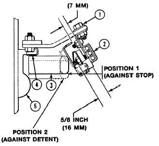
Loosen two screws (1) and slide switch (2
as far as possible horn hull.
Lock ramp door handle (3) against stop (4)
(see position 1 in illustration).
Slide switch (2) against handle (3) to get
approximately 1/4 inch (7 mm) clearance.
Tighten screws (l).
Move handle (3) against detent (5)
(see position 2 in illustration). Clearance
should be approximately 5/8 inch (16 mm).
From this setting, check switch for proper
function. Interior lights (white should come
on and blue light should be off. When
handle (3) is in first position
(see illustration) interior lights (white)
should be off and blue lights should be on.
Do steps 13 thru 16 and make adjustments
until the switch function produces the
correct result as stated herein.
F O L L O W - T H R O U G H S T E P S
1. Turn MASTER SWITCH ON (see your -10).
3. Turn all switches OFF’ (see your -10.
2. Turn on dome lights and open ramp access
4. Turn MASTER SWITCH OFF (See your -10).
door. All dome lights should go off and
blackout lights should come on.
END OF TASK
12-75