TM 9-2350-261-20-2
R E P L A C E R E A R M A I N W I R I N G H A R N E SS
( M 5 7 7 A 2 A N D M 1 0 6 8 O N L Y)
D E S C R I P T I O N
This task covers: Remove (page 12-82). Install (page 12-94).
I N I T I A L S E T U P
Tools:
References:
General Mechanics Tool Kit (Item 30, App D)
see your -lo
TM 11-7010-256-12&P
Materials/Parts:
Gasket
Equipment Conditions:
Grommet (12)
Engine stopped/shutdown (see your -10)
Lockwasher, as needed
Carrier blocked (see your -10)
None-electrical wire (Item 31, App D),
Ramp lowered (see your -10)
as needed
FAX removed (see TM 11-7010-256-12&P)
Self-locking nut (8)
Access to batteries (See Check Carrier
Batteries in your -10))
Personnel Required:
Battery ground leads disconnected (page 13-2)
Unit Mechanic
Rear floor plate removed (page 24-37)
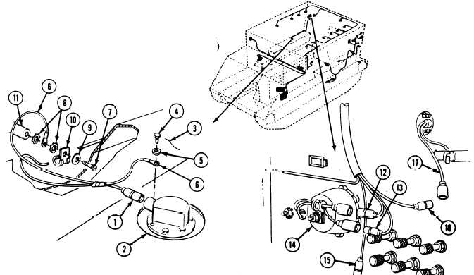
R E M O V E
4.
1.
2.
Disconnect circuit 29 lead (1) from right fuel
quantity sending unit (2).
5.
Remove Iockwire (3), screw (4),
lockwasher (5), and ground lead (6) from
6.
sending unit (2). Discard lockwire and
Iockwasher.
Disconnect circuits 23 and 24 leads
(12 and 13) from right tail light (14).
If NBC unit is installed, disconnect circuit
415 lead (15) from NBC unit switch.
Disconnect circuit 37A lead (16) from right
utility outlet lead (17).
3. Remove three screws (7), two
lockwashers (8), flat washer (9), ground lead
(6), three clamps (10), and circuit 29 lead (1)
from three weldnuts (11). Discard
lockwashers.
12-82
Change 3