TM 9-2350-261-20-2
R E P L A C E P A N E L A N D I N D I C A T O R L I G H T S
DESCRIPTION
This task covers:
Remove (page 11-5).
Install (page 11-6).
INITIAL SETUP
Tools:
References:
General Mechanics Tool Kit (Item 30, App D)
see your -10
Materials/Parts:
Equipment Conditions:
Light bulb, as needed
Engine stopped/shutdown (see your -10)
Lockwasher (2)
Carrier blocked (see your -10)
Preformed packing, as needed
MASTER SWITCH OFF (see your –10)
Personnel Required:
Unit Mechanic
REMOVE
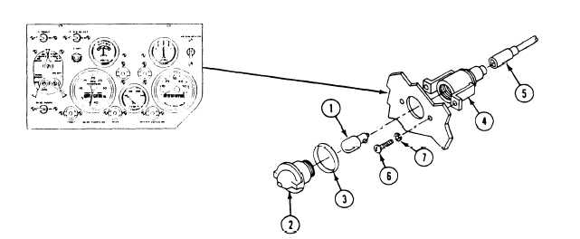
NOTE
There are two panel lights and three
indicator lights on the instrument panel.
Remove all lights the same way except for
the number of leads.
2.
1. Remove light bulb ( 1).
a.
b.
Turn lens (2) to the left. Remove lens (2)
and preformed packing (3) from light as-
sembly (4). Discard packing if damaged.
Push in and turn light bulb (1) to the
left, and remove bulb (I) from light
assembly (4).
N O T E
Do not disconnect more than one light at
a time. Mark each lead to make sure you
reconnect to correct contacts. See wiring
diagram (FO-2).
If required, remove light assembly (4).
a.
b.
Disconnect circuit lead (5) from light
assembly (4).
Remove two screws (6), lockwashers (7),
and light assembly (4) from instrument
panel. Discard lockwashers.
GO TO NEXT PAGE
11-5