TM 9-2350-261-20-2
R E P L A C E I N S T R U M E N T P A N E L M O U N T S A N D G R O U N D L E A DS
DESCRIPTION
This task covers:
Remove (page 11-2).
Install (page 11-3).
INITIAL SETUP
Tools:
References:
General Mechanics Tool Kit (Item 30, App D)
See your -10
See your -24P
Materials/Parts:
Lockwasher (4)
Equipment Conditions:
Self-locking nut (4)
Engine stopped/shutdown (see your -10)
Battery ground lead disconnected (page 13-2)
Personnel Required:
Unit Mechanic
R E M O VE
3.
1.
2.
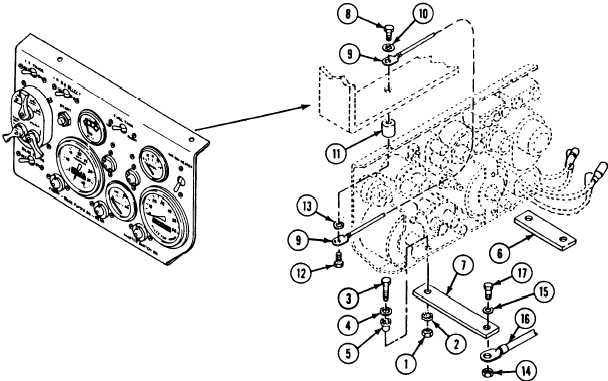
Remove two locknuts (1), bottom mounts (2),
screws (3), flat washers (4), and top mounts
(5) from two struts (6 and 7) and instrument
panel. Discard locknuts.
4.
Support instrument panel and remove two
bolts (8), ground lead (9), and two
lockwashers (10) from two resilient mounts
(11) and upper support bracket. Discard
lockwashers.
Tip instrument panel forward and remove two
bolts (12), ground lead (9), two lockwashers
(13), and resilient mounts (11) from
instrument panel. Discard lockwashers.
Remove two locknuts (14), washers (15),
auxiliary power receptacle ground lead (16),
two screws (17), short strut (6), and long
strut (7) from hull mounts. Discard locknuts.
NOTE
G r o u n d l e a d ( 1 6 ) i s n o t i n s t a l l e d o n t h e
M577A2 or M1068 instrument panel strut.
11-2
Change 3