TM 9-2350-261-20-2
29.
30.
31.
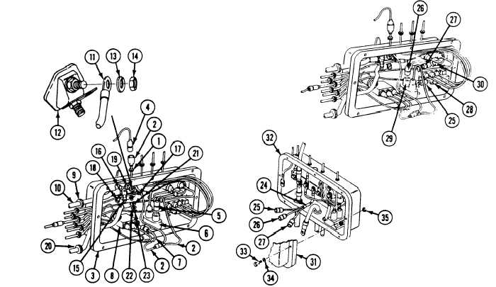
Install a new grommet (1) and wiring har-
ness (2) in master switch panel (3).
Connect wiring harness (2) tO circuit 38E
lead (4). Connect circuit 10 lead (5) on cir-
cuit breaker (6). Connect circuit 10 lead (7)
on dome light switch (8).
Install a new grommet (9)
lead (10) in master switch
N O T E
and circuit 6
panel (3).
32.
33.
Step 32 is for 200 amp generator only. All
other steps are common.
For 200 amp generator system, install cir-
cuit 2A lead (11) on top
switch (12) . Secure with
(13) and nut (14).
Install circuits 6, 2, and
terminal of master
new lockwasher
400 leads (10, 16,
and 16) on bus bar (17)
(18) and nut (19).
. Secure with screw
34.
35.
36.
37.
38.
Install new grommet (20) and circuit 49
lead (21) in master switch panel
assembly (3).
Install circuit 49 lead (21) on bottom ter-
minal of master switch (12). Secure with
washer (22) and nut (23).
Connect wiring harness (24) leads
(25, 26, and 27) to three circuit breakers
(28, 29, and 30).
Replace gasket between master switch panel
and distribution box, if damaged
(page 12-25).
Install master switch panel (31) on
distribution box (32). Secure with eight
screws (33), washers (34), and new
locknuts (35).
FOLLOW-THROUGH STEPS
1. Connect battery ground lead (page 13-2).
3. Stop/shutdown engine (see your -10).
2. Start engine (see your -10). Check that
master switch panel assembly is operable.