TM 9-2350-261-20-2
15.
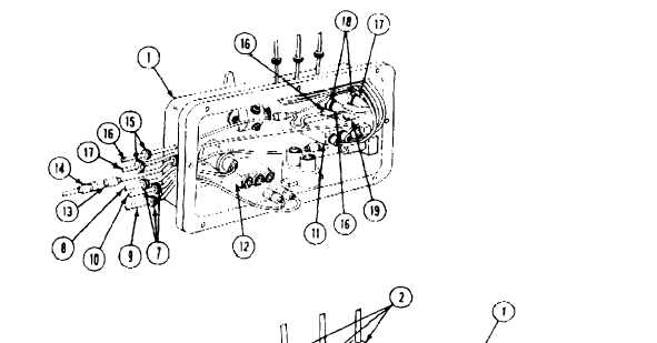
Disconnect circuits 38A and 38 leads
(9 and 10) from dome light switch (12).
16.
Remove circuits 37A, 38, 38A leads
(8, 10, and 9) and three grommets (7) from
master switch panel (1). Discard grommets.
17. Disconnect circuits 28, 29, and 30 leads
(3, 4, and 5) from fuel selector switch (6).
18. Remove circuits 28, 29, 30 leads
(3, 4, and 5) and three grommets (2) from
master switch panel (1). Discard grommets.
19. Remove master switch panel assembly (1)
from carrier.
9-24
INSTALL
20. Install three new grommets 92) and circuits
28, 29, and 30 leads (3, 4, and 5) in
master switch panel (1).
21. Connect circuits 28, 29, and 30 leads (3, 4,
and 5) to fuel selector switch (6).
22. Install three new grommets (7) and circuits
37A, and 38, and 38A leads (8, 9, and 10) in
master switch panel assembly (1).
23. Connect circuit 37A lead (8) to circuit
breaker (1).
24. Connect circuits 38 and 38A leads (9 and
10) to dome light switch (12).
25. Connect utility outlet lead (13) to circuit 37
lead (14).
26. Install two new grommets (15), wiring har-
ness (16), and circuit 59 lead (17) in master
switch panel (1).
27. Connect wiring harness 916) to blower
switch (18) and to circuit 37B lead on cir-
cuit breaker (19).
28. Connect circuit 59 lead (17) to blower
switch (18).