TM 9-2350-261-20-1
NOTE
Do steps 26.1 thru 26.9 on M1064 only.
26.1
26.2
26.3
26.4
26.5
26.6
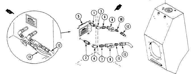
Apply sealing compound (Item 50) to pipe
threads on adapters (1 and 2) and
elbows (3 and 4).
Install adapters (1 and 2) in fuel
tank (5).
Install elbows (3 and 4) on
adapters (1 and 2).
Install adapters (6 and 7) on
elbows (3 and 4).
Install fuel return valve (8) on adapter (6)
with arrow pointing toward fuel tank.
Install fuel supply valve (9) on adapter (7)
with arrow pointing toward the engine.
26.7 Install adapters (10 and 11) in
valves (8 and 9).
26.8 Connect fuel return hose (12) to
adapter ( 10).
26.9 Connect fuel supply hose (13) to
adapter (11).
NOTE
The four spare electrical mounting holes
will always be the holes located on the
outer edge of each fuel tank. The
electrical guards are always mounted on
the inner edge of each fuel tank.
27.
Install four setscrews (14) in spare holes
provided for electrical mounting.
FOLLOW-THROUGH STEPS
1.
Install filler caps and strainers (page 6-30).
7.
Cable reel holder assembly installed
(page 41-7).
2.
Install filler covers and locks (page 6-29).
8.
Fill fuel tanks (see your –10).
3.
Install fuel quantity transmitter
(page 6-32).
9.
Start engine (see your –10). Check for
leaks.
4.
Install fuel tank access covers (page 6-31).
5.
Install guards and tail lights (page 12-57).
6.
Connect battery ground lead (page 13-2).
10.
Raise and lock ramp (see your –10).
11.
Install track shrouds (page 22-2).
END OF TASK
6-38
Change 2