TM 9-2350-261-20-1
NOTE
Both fuel tanks are removed from carrier
the same way (left side fuel tank shown).
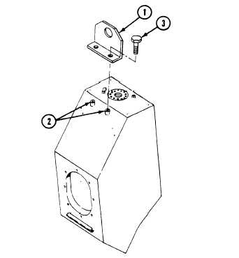
Use tail light bracket screws to secure
lifting bracket to fuel tank.
7.
Install angle lifting bracket (1) on tail light
9.
Remove five screws (5), washers (6), and
gasket (7), from fuel tank (8). Discard
gasket. Remove fuel tank from carrier.
Have helper assist.
bracket mounting holes (2). Secure
screws (3). Attach lifting device to
bracket.
with two
lifting
NOTE
Both fuel tanks are installed on carrier
the same way (left side fuel tank shown).
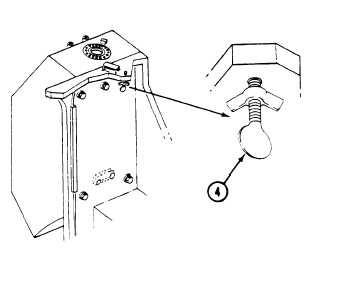
8.
Remove fuel cap locking thumbscrew (4)
from inside earner.
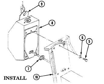
10.
11.
Apply thin coat of sealing compound
(Item 52) to new gasket (7) and to gasket
mating surface on fuel tank (8). When
sealing compound has become tacky,
install gasket on tank.
Attach lifting device to lifting bracket (9).
Position fuel tank (8) to rear hull plate
(10). Have helper assist.
NOTE
Inside of mounting holes and full diame-
ter area under each washer must be free
of paint to ensure a good electrical
ground.
12.
13.
14.
Apply molybdenum D grease to threads of
five screws (5).
Secure fuel tank (8) to rear hull plate (10)
with five screws (5) and washers (6).
Tighten screws to 270-295 lb-ft
(366-400 N•m) torque. Use torque wrench
and socket wrench set. Have helper assist.
Apply caulking compound to space around
installed screw heads and washers on rear
hull plate (10). Do not apply compound to
screw threads.
6-36
Change 2