TM 9-2350-287-20-1
8-2. SHIFT CONTROL LINKAGE REPAIR (continued).
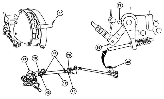
21.
Loosen two nuts (44) on assembled rod (17).
22.
Disconnect quick-release pin (16) and remove assembled rod (17) from control assembly (24).
23.
Recheck to see that lever (39) is in neutral (N) position at shift control lever index (79).
24.
Adjust length of assembled rod (17), turning both bearings (43) until quick-release pin (16) can be installed easily
into control assembly (24) and through bearings (43).
25.
Tighten two nuts (44) against bearings (43) of assembled rod (17), checking witness holes (78) on bearings (43).
WARNING
Verification of shift positions must be performed prior to starting engine. Failure
to do so may result in injury to personnel or damage to vehicle.
26.
Move shift selector (77) through all positions. Check to see that shift selector setting in driver's compartment is
same as shift control lever index (79) on transmission at all positions.
FOLLOW-ON MAINTENANCE:
Close transmission access doors (refer to TM 9-2350-287-10).
Close drivers hatch cover (refer to TM 9-2350-287-10).
Change 1 8-17