TM 9-2350-287-20-1
8-2.
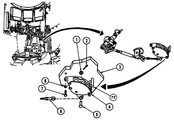
SHIFT CONTROL LINKAGE REPAIR (continued).
12.
Install shift quadrant (4) on bulkhead (3) with three screws (7) and new lockwashers (8).
13.
Install assembled rod (6) on shift quadrant (4) with pin (5), washer (1), and new cotter pin (2).
f.
ADJUSTMENT
1.
Place shift selector (77) in neutral (N) position. Maintain neutral position.
2.
Remove cotter pin (10), washer (9), pin (12), and assembled rod (6) from bellcrank (63). Discard cotter pin.
3.
Position bellcrank (63) parallel to lever assembly (58) and in vertical position.
NOTE
Bellcrank arm must remain parallel to lever assembly arm as part of adjustment.
4.
Loosen two nuts (44) on assembled rod (6).
5.
Adjust length of assembled rod (6), turning both bearings (43) until pin (12) can be installed easily into bellcrank
(63) and through bearings (43).
6.
Install washer (9) and new cotter pin (10) on pin (12).
7.
Tighten two nuts (44) against two bearings (43). After adjustment is complete, check to see that witness holes
(78) on bearings (43) are closed by inserting small wire into each hole.
Change 1 8-14