TM 9-2350-277-34
REPAIR SIGNAL PATCH PANEL BOX A10 (M1068A3 ONLY) — Continued
0099 00
ASSEMBLY
1.
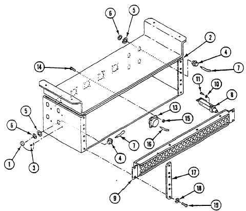
If dust caps (1) were removed, install dust caps on signal patch panel box (2) and secure with new rivets (3).
2.
Install eight connectors (4) on signal patch panel box (2), secure with lockwashers (5) and jamnuts (6).
NOTE
Install wires (7) on eight connectors (4) using wiring diagram page 0099 00–3.
Apply primer and sealant to threads of screws (11).
3.
Install 156 jacks (8) on three jackfields (9), secure with new lockwashers (10) and screws (11).
NOTE
Install two leads (12) on each jack (8) using wiring diagram page 0099 00–3.
4.
Install five connectors J135, J136, J138, J139, and J140 (13) on signal patch panel box (2), secure with twenty screws
(14) and new locknuts (15).
NOTE
Install wires (16) on five connectors J135, J136, J138, J139, and J140 (13), using wiring diagram
page 0099 00–3.
5.
Install three jackfields (9) on signal patch panel box (2), secure with two strips (17), twelve new lockwashers (18), and
screws (19).
0099 00-4