TM 9-2350-277-34
REPAIR SIGNAL PATCH PANEL BOX A10 (M1068A3 ONLY) — Continued
0099 00
NOTE
Tag all wires/leads before removal, use wiring diagram page 0099 00–3.
2.
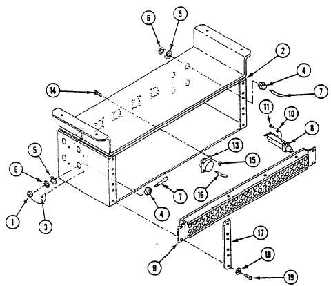
Remove twenty locknuts (15), screws (14), and five connectors J135, J136, J138, J139, and J140, (13) from signal patch
panel box (2). Discard locknuts.
3.
Disconnect wires (16) from five connectors J135, J136, J138, J139, and J140 (13).
4.
Remove screws (11), lockwashers (10), and 156 jacks (8) from three jackfields (9). Discard lockwashers.
5.
Remove two leads from each jack (8).
6.
Remove jamnuts (6), lockwashers (5), and eight connectors (4) from signal patch panel box (2).
7.
Remove wires (7) from eight connectors (4).
8.
If dust caps (1) are damaged, remove rivets (3) and dust caps from signal patch panel box (2).
0099 00-2