TM 9-2350-277-34
REPAIR SIGNAL PATCH PANEL BOX A10 (M1068A3 ONLY)
0099 00
THIS WORK PACKAGE COVERS:
Disassembly (page 0099 00-1).
Assembly (page 0099 00-4).
INITIAL SETUP:
Maintenance Level
Direct Support
Tools and Special Tools
Electronic Equipment Tool Kit (WP 0120 00, Item 61)
Materials/Parts
Sealing compound (WP 0122 00, Item 25)
Adhesive primer (WP 0122 00, Item 23)
Lockwasher (as required)
Locknut (20)
Rivet (as required)
Personnel Required
Radio Repairer 29E10
References
See your -20
Equipment Condition
Signal patch panel box removed (see your -20)
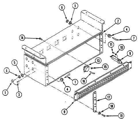
DISASSEMBLY
1.
Remove twelve screws (19), lockwashers (18), two strips (17), and three jackfields (9) from signal patch panel box (2).
0099 00-1