TM 9-2350-277-20-4
REPLACE PUSH-PULL CONTROL ASSEMBLY, BRACKET, LINKS, AND PINS
(CABLE-ACTIVATED LOCK) — Continued
0429 00
ADJUSTMENT
1.
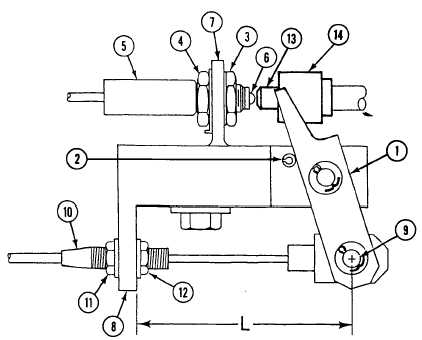
Use a 6-inch ruler to measure the distance from bracket housing (8) to center of rod end pin (9).
2.
Place transmission controller in SL position.
3.
Adjust push-pull control assembly (10) at jamnuts (11) and (12) so that links are 1/2 inch from their retracted position as
follows:
a.
With transmission controller in SL position, measure the distance from bracket (8) to the center of pin (9). Record
distance as L1.
b.
Move the transmission controller out of SL position.
c.
Measure the distance from bracket (8) to the center of pin (9). Record distance as L2.
d.
The difference between the measured distances L2 minus L1 must be 1/2 inch ± 1/32 inch (12.7 mm ±.8 mm).
e.
Adjust jamnuts (11) and (12) to get 1/2 inch adjustment. Tighten jamnuts.
0429 00-12