TM 9-2350-277-20-4
REPLACE PUSH-PULL CONTROL ASSEMBLY, BRACKET, LINKS, AND PINS
(CABLE-ACTIVATED LOCK) — Continued
0429 00
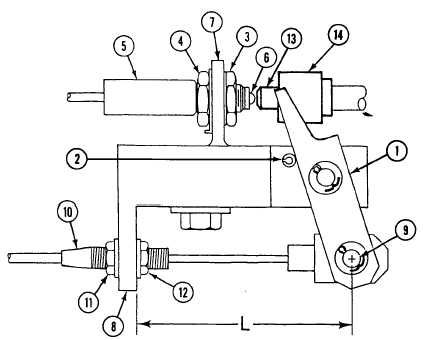
13. With the links (1) resting on spring pin (2), loosen two jamnuts (3) and (4) on switch (5).
NOTE
Make sure switch plunger is contacting end of locking pin while adjusting switch.
14. Push switch (5) in until switch plunger (6) is fully depressed.
15. Turn jamnut (3) until it touches bracket (7), then turn it back one half turn.
16. Tighten second jamnut (4) to secure switch (5) to bracket (7).
17. Install block (14) and locking pin (13) between links (1).
0429 00-11