TM 9-2350-277-20-4
REPLACE PUSH-PULL CONTROL ASSEMBLY, BRACKET, LINKS, AND PINS
(CABLE-ACTIVATED LOCK) — Continued
0429 00
1.
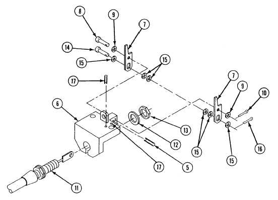
Install three new spring pins (17) and (5) on bracket (6).
2.
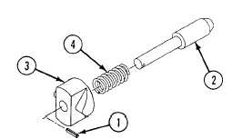
Install spring (4) on locking pin (2).
3.
Install block (3) on locking pin (2) with new pin (1).
4.
Install links (7) to bracket (6) by aligning the center holes of the links with the uppermost holes of bracket (6) and
inserting pin (8), washers (9), and new cotter pin (10).
5.
Install push-pull control assembly (11), new lockwasher (12), and nut (13) on bracket (6).
NOTE
Washers are also used as shims to insure proper fit and to center end of push-pull assembly.
6.
Install pin (14), links (7), washers (shims) (15) as needed, push-pull control assembly (11), and new cotter pin (16).
0429 00-8