TM 9-2350-277-20-4
REPLACE PUSH-PULL CONTROL ASSEMBLY, BRACKET, LINKS, AND PINS
(CABLE-ACTIVATED LOCK) — Continued
0429 00
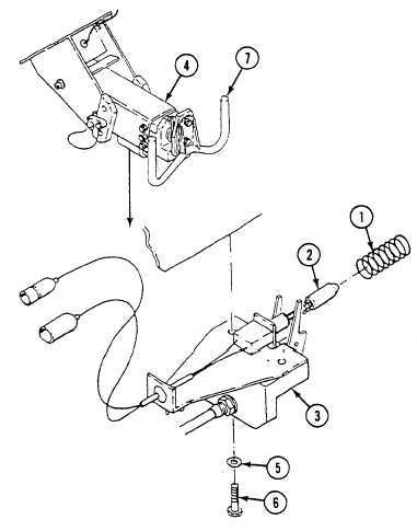
8.
Turn the steering wheel (7) left and right to insure the locking pin is not interfering with operation.
9.
Measure the locking pin (2) to see if it is flush with the steering wheel housing (4). The locking pin must be flush and
can have only a negative tolerance. It can be a maximum recess of 1/16 inch (1.6 mm). This measurement is maintained
for all positions of the transmission controller except the SL position.
WARNING
With the transmission controller in any range except SL and if the locking pin is protruding
from the steering wheel housing any amount, the steering wheel will not turn properly and
death of personnel or damage of equipment may occur.
10. Loosen two screws (6) and adjust the bracket (3) until the locking pin is flush or maximum 1/16 inch (1.6 mm) recessed.
Tighten two screws (6).
0429 00-14