TM 9-2350-277-20-3
REPLACE AUXILIARY POWER (SLAVE) RECEPTACLE (M113A3, M901A3,
M1059A3, M1064A3, AND M58 ONLY)
0263 00
THIS WORK PACKAGE COVERS:
Removal (page 0263 00-1).
Installation (page 0263 00-2).
INITIAL SETUP:
Maintenance Level
Unit
Tools and Special Tools
General Mechanic’s Tool Kit (WP 0926 00, Item 65)
Materials/Parts
Locknut (4)
Locknut (8)
Personnel Required
Unit Mechanic
References
See your -10
Equipment Condition
Engine stopped (see your -10)
Carrier blocked (see your -10)
Battery ground strap disconnected (WP 0337 00)
Warning light panel assembly removed (WP 0291 00)
REMOVAL
1.
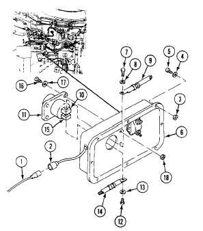
Disconnect circuit 37 lead (1) from connector (2).
2.
Remove eight locknuts (3), washers (4), screws (5), and master switch panel (6) from distribution box. Discard locknuts.
3.
Remove screw (7), lockwasher (8), and circuit 50 lead (9) from positive post (10) of auxiliary power receptacle (11).
4.
Remove screw (12), lockwasher (13), and ground strap (14) from negative post (15) of receptacle (11).
5.
Remove four screws (16), washers (17), locknuts (18), and receptacle (11) from master switch panel (6). Discard
locknuts.
0263 00-1