TM 9-2350-277-20-3
REPLACE UTILITY OUTLET RECEPTACLE (ALL EXCEPT M981A3)
0265 00
THIS WORK PACKAGE COVERS:
Removal (page 0265 00-1).
Inspection and Repair (page 0265 00-2).
Installation (page 0265 00-2).
INITIAL SETUP:
Maintenance Level
Unit
Tools and Special Tools
General Mechanic’s Tool Kit (WP 0926 00, Item 65)
Multimeter (WP 0926 00, Item 30)
Materials/Parts
Locknut (8)
Lockwashers (2)
Personnel Required
Unit Mechanic
References
See your -10
Equipment Condition
Engine stopped (see your -10)
Carrier blocked (see your -10)
Battery ground lead disconnected (WP 0337 00) or
(WP 0338 00)
Warning light panel assembly removed (WP 0291 00)
REMOVAL
1.
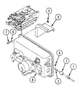
Disconnect circuit 37 lead (1) from utility outlet receptacle lead (2).
2.
Slide shell connector (3) down lead (2). Remove slotted washer (4) from lead. Remove shell connector from lead.
3.
Remove eight locknuts (5), washers (6), screws (7) and master switch panel (8) from distribution box (9). Discard
locknuts.
0265 00-1