TM 9-2350-277-20-3
REPLACE MASTER SWITCH (M113A3, M901A3, M1059A3, M1064A3, AND
M58 ONLY)
0262 00
THIS WORK PACKAGE COVERS:
Removal (page 0262 00-1).
Installation (page 0262 00-2).
INITIAL SETUP:
Maintenance Level
Unit
Tools and Special Tools
General Mechanic’s Tool Kit (WP 0926 00, Item 65)
Materials/Parts
Locknut (2)
Locknut (8)
Lockwasher (2)
Personnel Required
Unit Mechanic
References
See your -10
Equipment Condition
Engine stopped (see your -10)
Carrier blocked (see your -10)
Battery ground strap disconnected (WP 0337 00)
Infrared power supply cable disconnected from master
switch panel (see your -10)
Warning light panel assembly removed (WP 0291 00)
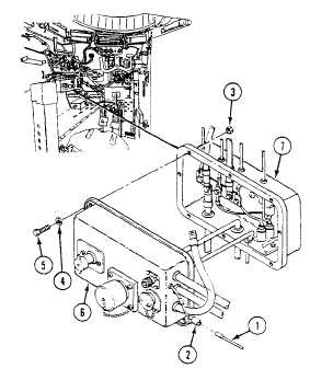
REMOVAL
1.
Disconnect circuit 37 lead (1) from connector (2) .
2.
Remove eight locknuts (3) , washers (4) , screws (5) , and master switch panel (6) from distribution box (7) . Discard
locknuts.
0262 00-1