STEERING CONTROL LINKAGE: REMOVAL, DISASSEMBLY, ASSEMBLY AND INSTALLATION
INITIAL SETUP
REMOVAL
Materials/Parts:
A
Lubricant, solid, wax base, Nylube 150 (item 72, Appx D)
B
Equipment Condition:
Vehicle tracks chocked
C
Open Transmission access doors.
Remove master warning light assembly from steering shaft mount (p 7-53).
NOTE
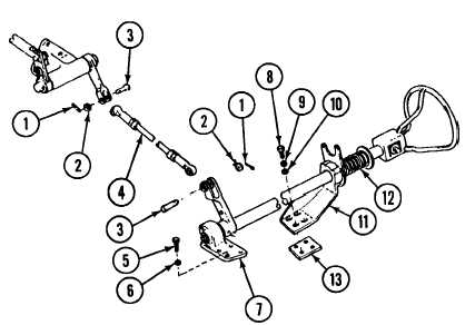
Rod assembly (4) is connected between steering shaft
and bulkhead-mounted housing.
Remove two cotter pins (1), two flat washers (2), two pins (3) and rod
assembly (4). Discard cotter pins.
D Remove four screws (5) and four lockwashers (6) from bracket (7). Discard
E
F
lockwashers.
Remove four screws (8), four lockwashers (9) and four flat washers from
bracket (11). Discard lockwashers.
Remove steering shaft assembly (12) with two brackets (7 and 11), and
spacer (13) from driver’s compartment.
7-11
Change 4
TM 9-2350-267-20