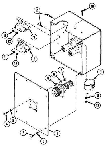
APU CONTROL BOX: REMOVAL, DISASSEMBLY, ASSEMBLY, CIRCUIT TEST AND INSTALLATION (CONTINUED)
DISASSEMBLY
A Remove rear panel (1) by removing four screws (2) and four
washers (3).
B
Remove four screws (4), four flat washers (5), four lockwashers
(6) and four nuts (7), and remove wiring harness connector (8)
from rear panel (1).
C
Remove wiring harness (8) by pulling harness connectors
from control box components.
D Disconnect and remove remaining wires from switches, cir-
cuit breakers and connectors inside box.
E
Remove three circuit breakers (9) by removing from each,
two screws (10), two lockwashers (11) and two nuts (12).
TA309983
13-37
TM 9-2350-267-20

