13-40
TM 9-2350-267-20
APU CONTROL BOX: REMOVAL, DISASSEMBLY, ASSEMBLY, CIRCUIT TEST AND INSTALLATION (CONTINUED)
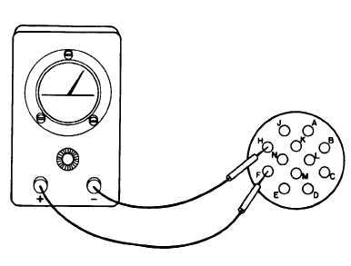
SHORT CIRCUIT TEST
A Place all switches in OFF position.
B Check for continuity between points listed below.
Multimeter should indicate continuity. Points that should
not indicate continuity are listed under Exceptions column.
RED PROBE
I
BLACK PROBE
I
EXCEPTIONS
A
B
C
D
F
H
J
K
L
M
N
CONNECTOR
BODY
ALL OTHER PINS
ALL OTHER PINS
ALL OTHER PINS
ALL OTHER PINS
ALL OTHER PINS
ALL OTHER PINS
ALL OTHER PINS
ALL OTHER PINS
ALL OTHER PINS
ALL OTHER PINS
ALL OTHER PINS
ALL OTHER PINS
NONE
NONE
NONE
NONE
F TO K, F TO J, F TO M
NONE
J TO M, J TO F, J TO K
K TO F, K TO GROUND
NONE
M TO J, M TO K, M TO F
NONE
BODY TO F, BODY TOM
C
If meter indicates short circuit, use schematic and illustra-
tion (p 13-35) to check internal wiring, circuit breakers and
switches.
INSTALLATION
Reverse removal procedures.
TA309986