12-36
TM 9-2350-267-20
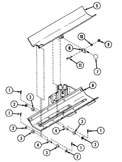
SLIDING TRAY ASSEMBLY: REMOVAL, DISASSEMBLY, ASSEMBLY AND INSTALLATION
REMOVAL
A Remove four cotter pins (1), four washers (2), four roller bear-
ings (3) and two pins (4) from tabs at bottom of sliding tray
assembly (5).
B Lift sliding tray assembly (5) from carrier (6).
DISASSEMBLY
A Unscrew knob (7) from handle (8).
B Remove nut (9), lockwasher (10) and bolt (11)
(8) to sliding tray (5).
ASSEMBLY
Reverse disassembly procedures.
INSTALLATION
securing handle
A Place sliding tray (5) on carrier (6) so that tab on tray bottom
protrudes through slot in carrier.
B Place two pins (4) through tray tab and two roller bearings (3)
on either side. Then secure both ends of each pin with one
washer (2) and one cotter pin (1).
TA310236