TA57274
12-34.2
Change 2
TM 9-2350-267-20
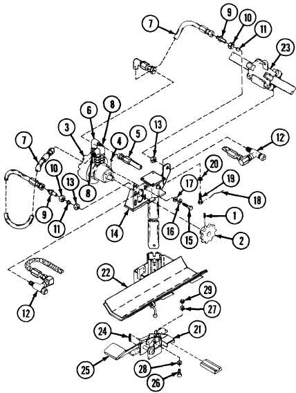
CARRIER ASSEMBLY AND MOTOR SUPPORT BRACKET: REMOVAL, INSTALLATION AND ADJUSTMENT (CONTINUED)
INSTALLATION
A
Slide carrier assembly (22) onto support bracket (14).
B
Install foot brake assembly (21) on support bracket (14), and
position foot pedal (25) to install screw (26), new lockwasher (27),
flat washer (28) and nut (29).
C
Install spring (24)
D Install support bracket (14), foot brake assembly (21) and car-
rier assembly (22) as an assembly on roller assembly (23) using
four screws (19) and four new lockwashers (20). Install new
lockwire (18) on screws (19).
E
Install hydraulic motor (3) on support bracket (14) with four
screws (15), four new lockwashers (16) and four flat washers (17).
F
Install two tee assemblies (12) on support bracket (14) with two
nuts (13).
G
Install two reducers (9), two nuts (10) and two sleeves (11) as
assemblies on two tee assemblies (12), by turning nuts (13).
H Connect two hoses (7) to two elbows (8) and two reducers (9)-
I
Connect hose (5) to elbow (6).
J
Install key (4) on shaft of motor (3).
K Install sprocket (2) on shaft of hydraulic motor (3) and tighten
setscrew (1).