TM 9-2350-261-34
I N S T A L L C O M M A N D E R ’ S C U P O L A A R M O R S H I E L D S ( M 1 1 3 A 2
M106A2, M125A2, M1059, AND M1064 ONLY)
INITIAL SETUP
Tools:
General Mechanics Tool Kit (Item 35, App B)
Portable Electric Drill (Item 23, App B)
Screw Threading Set (Item 79, App B)
Trailer Mounted Welding Shop
(Item 96, App B)
Twist Drill Set (Item 98, App B)
Materials/Parts:
Machine Gun Shield Kit 11660854 (19207)
Spacer, 1/16-1/8 inch thick (2)
Wood blocks of equal height (2)
Personnel Required:
Track Vehicle Repairer 63H10
Helper
References:
See your –10
TM 43-0139
TM 9-237
Equipment Conditions:
Engine stopped (see your –10)
Carrier blocked (see your –10)
INSTALL
1.
2.
3.
4.
5.
If four shield mounting holes are already
drilled in cupola hatch, remove and discard
four 1/2–13 screws and flat washers from
hatch. If mounting holes are NOT drilled,
follow steps 3 thru 5.
Remove two 5/8-18 screws (1) and
washers (2) from outboard support legs of
machine gun pintle (3). Discard screws. Keep
flat washers.
Remove machine gun mount and support
from cupola. Close cupola (see your –10).
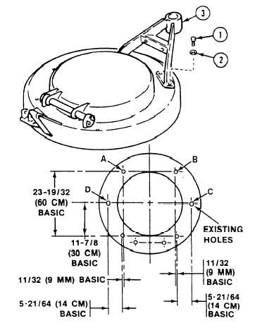
N O T E
All dimensions are in inches with metric
equivalents.
Measure and mark four points (A, B, C,
and D) on cupola shown at right. Measure
point positions from four existing screw holes
that secure machine gun support to cupola.
Drill four holes using 27/64 (11 mm) drill.
Drill to a maximum depth of 1-1/4 (3 cm).
Tap with a 1/2–13 UNC tap to a minimum
depth of 7/8 (22 mm).
20-2
Change 2