TM 9-2350-261-34
FUEL FLOW TEST
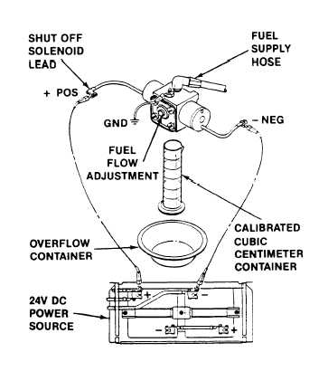
Connect fuel control valve to coolant heater
fuel hose. Fuel pressure must be 3 to 15 psi
(21 to 103 kPa), when fuel valve is open.
Place fuel control valve outlet over calibrated
and overflow containers.
Make sure the body of fuel valve is
grounded.
Energize fuel valve solenoids. Connect two
solenoid leads to a 24 V dc power source.
Solenoids are now open for high heat fuel
flow .
W A R N I NG
10.
11.
12.
Sparks from static electric-
ity could cause a tire or
explosion.
Make sure to
ground the coolant heater
before you open fuel supply
valve.
Open coolant heater fuel supply valve
(page 14-16, 14–31, or 14-47). Bleed fuel
hose in a suitable container.
After fuel flow is stable, place calibrated
container under fuel control valve.
Allow fuel to flow for exactly 1 minute then
close coolant heater fuel supply valve. Con-
tainer should contain 14 + 2 cubic centime-
ters of fuel.
13. Repeat steps 1 thru 7 with shutoff solenoid
side only of fuel control valve energized with
14.
15.
24 V dc.
Calibrated cubic centimeter glass container
should now contain 8.5 + 2 cubic centime-
ters of fuel.
If fuel flow rates are not within limits,
adjust flow. Turn adjusting screw to right
to increase and to left to decrease. Adjust
high heat flow first, then low heat flow.
16.
17.
After fuel flow is adjusted within limits,
seal adjusting screw with insulating varnish.
If fuel flow cannot be adjusted within limits,
replace fuel control valve.
LEAK TEST
18.
19.
20.
Repeat high heat fuel flow test. Disconnect
both solenoid leads from 24 V dc power
source.
One or two drops of fuel may form after
solenoid leads are disconnected from power
source. Further leakage is not acceptable.
Replace fuel control valve that leaks.
GO TO NEXT PAGE
14-49
6.
7.
8.
9.