TM 9-2350-261-34
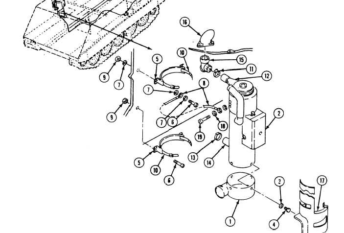
17. Secure plenum (1) to heater (2) with four
lockwashers (3) and screws (4).
N O T E
Four nuts and screws were previously
removed and retained. However, on the
M113A2 carrier, screw that secures strap
is supplied in the personnel heater kit.
18.
19.
20.
Secure two saddles (5) to power plant
bulkhead with four retained screws (6),
three lockwashers (7), ground strap (8) and
four retained nuts (9).
Install two clamps (10) in two saddles (5).
Position clamp (11) on heater intake
pipe (12) and place clamp (13) on heater
exhaust pipe (14). Do not tighten.
22.
23.
24.
25.
26.
Install elbow (15) in heater intake pipe (12)
and intake elbow (16).
Align inlet elbow (15) with intake elbow
(16), and align exhaust pipe (14) with
exhaust pipe in carrier. Place heater (2) and
shield (17) (M113A2 only) against
saddles (5).
While still supporting heater, double check
for proper mating of heater exhaust
port (14) and exhaust pipe in earner.
Tighten two saddle clamps (10).
Position ground strap (8) on heater (2) and
secure with (one M113A2) (two M741A1)
lockwasher(s) (18) and screw (19) (741A1
use existing screw) (M113A2 discard existing
screw and use kit screw).
Tighten clamp (13) on heater exhaust
pipe (14) and exhaust pipe in carrier.
Tighten clamp (11) on heater intake
pipe (12).
11-4
21.