TM 9-2350-261-34
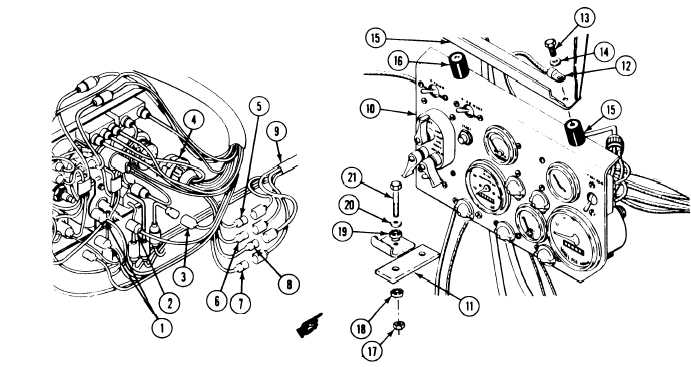
98. Connect two circuit 40 leads (1) to
103.
instrument panel lights.
99. Connect circuit 452B lead (2) to bilge pump
104.
ON light.
100. Connect circuit 452A lead (3) to bilge
pump switch.
101. Connect connector (4) to light selector
switch.
102. Connect circuit 24, 23, 22, and 21 leads
(5, 6, 7, and 8) to rear main wiring
harness (9).
105.
106.
Support instrument panel (10) on two
struts (11).
Install ground lead (12), two screws (13),
and flat washer (14) on upper
support (15).
Install panel (10) with two mounts (16) on
upper support (15). Secure with two
screws (13).
Install panel (10) on two struts (11).
Secure with two new locknuts (17), mounts
(18 and 19), flat washers (20), and
screws (21).
F O L L O W - T H R O U G H S T E P S
1. Install driver’s power plant access cover
4.
(see your –20).
2. Close power plant front access door and raise
trim vane (see your -10).
5.
3. Connect battery ground lead (see your –20).
6.
Start engine (see your -10). Check that
master switch panel, instrument panel, and
distribution box operate properly.
Check that lights operate properly
(see you= -10).
Stop/shutdown engine. (see your –10).
END OF TASK
6-32
Change 2