TM 9-2350-261-34
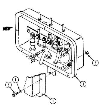
90. Install master switch panel assembly (1) on
distribution panel (2). Secure with eight
nuts (3), washers (4), and screws (5).
91. Route front main wiring harness (6) up
92.
93.
94.
95.
96.
97.
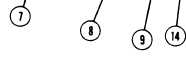
Connect circuit 406 lead (7) to air box
heater switch.
Connect circuit 33 lead (8) to engine
coolant temperature gage.
Connect circuit 74 and 14 plug (9) to
starter switch.
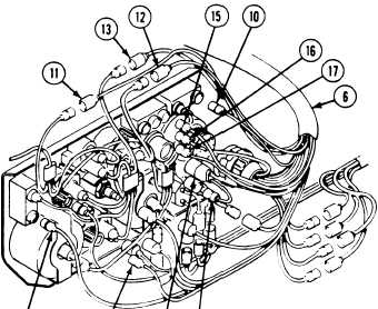
Connect circuit 516A lead (10) to infrared
(1. R.) power selector switch.
Connect circuit 15, 25A, 27F, and 14 leads
(11, 12, 13, and 14) to instrument panel
wiring harness.
Connect circuit 19, 520, and 514-515 leads
(15, 16, and 17) to infrared blackout
(1.R. - B. O.) switch.
behind instrument panel. Follow steps 91
thru 101 to attach leads to panel.
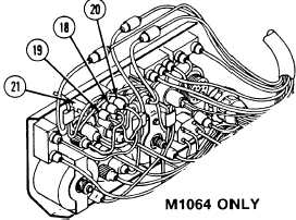
N O T E
Step 97.1 applies to M1064 only.
97.1 Install circuits 28 (18), 30 (19), and 31
(20) on fuel tank switch (21).
GO TO NEXT PAGE
Change 2
6-31