TM 9-2350-261-34
83.
84.
Install harness (1) on wall of driver’s com-
partment. Secure to three weldnuts (2) and
cradles (3) with three clamps (4), washers
(5), screws (6), and clip (7).
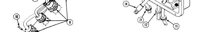
Install four connectors (8) on driver’s
bulkhead. Secure with 16 nuts (9) and
screws (10). Have helper assist.
89. On 200 amp generator system, install
circuit 2A lead (13) and circuit 2 lead (14)
in master switch panel assembly
(see your –20).
FOR 200 AMP GENERATOR SYSTEM
u
85.
86.
87.
88.
INSIDE DRIVER’S
COMPARTMENT
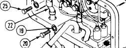
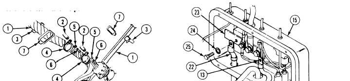
On 200 amp generator system, install two
new grommets (11 and 12), circuit 2A lead
(13), and circuit 2 lead (14) in distribution
box (15).
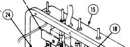
On 100 amp generator system, install new
grommet (16) and circuit 3 lead (17) in
distribution box (15). Install circuit 3 lead
on circuit breaker (18) and secure with new
lockwasher (19) and screw (20).
Install new grommet (21) and circuit 6 lead
(22) in distribution box (15). Install circuit 6
lead on bus bar (23). Secure with new
lockwasher (24) and screw (25).
On 100 amp generator system, install new
grommet (26) and circuit 2 lead (27) in
distribution box (15). Install circuit 2 lead in
master switch panel assembly
(see your -20).
FOR 100 AMP GENERATOR” SYSTEM
6-30