TM 9-2350-261-20-2
N O T E
13.
M741A1 carriers and carriers that have
1 0 0 A m p G e n e r a t o r s d o n o t h a v e
Circuit 2A.
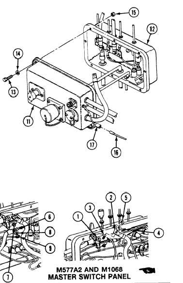
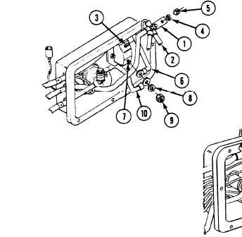
10. Install conductor bus (1) with attached
14.
leads, and circuit 2A lead (2) on terminal
(3). Secure with new lockwasher (4) and
nut (5).
N O T E
On M577A2 and M1068 earners do step 11,
then go to step 13. On all other earners,
after step 10, go to step 12.
11.
12.
Install circuit 49 lead (6) on master switch
(8) and nut (9).
Install circuit 49 lead (6) and circuit 50 lead
(10) on terminal (7). Secure with new
lockwasher (8) and nut (9).
Install master switch panel (11) on
distribution box (12). Secure with eight
screws (13), washers (14), and new
locknuts (15).
Connect circuit 37 lead (16) to connec-
tor (17).
terminal (7). Secure with new lockwasher
FOLLOW-THROUGH STEPS
1. Connect battery ground lead (page 13-2).
3.
.
2. Turn MASTER SWITCH ON (see your -10.
4.
MASTER SWITCH light should come on
(see your -10).
Turn MASTER SWITCH OFF (see your -10).
END OF TASK
Change 3
9-15