TM 9-2350-261-20-2
INSTALL
10.
11.
12.
13.
14.
15.
16.
17.
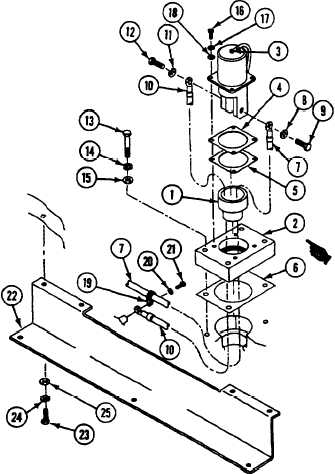
Install insulator bushing (1) in adapter (2).
Install receptacle (3) new gasket (4),
insulator (5), adapter (2), and new
gasket (6) on hull.
Connect circuit 6 lead (7) to positive
terminal of receptacle (3) with new
lockwasher (8) and screw (9).
Connect circuit 50 lead (10) to negative
terminal of receptacle (3) with new
lockwasher (11) and screw (12).
Position new gasket (6) and adapter (2) on
hull and secure with four screws (13), new
lo&washers (14), and washers (15).
Align receptacle (3), new gasket (4), and
insulator (5) with adapter (2). Install four
screws (16), new lockwashers (17), and
washers (18).
Place circuit 50 lead (10) and clamp (19) on
hull weldnut. Secure with washer (20) and
screw (21).
Position harness protector (22) and secure
with seven screws (23), new
lockwashers (24), and washers (25).
FOLLOW-THROUGH STEPS
1. Connect battery ground lead (page 13-2).
2. Check receptacle for electrical continuity
(page 3-5).
END OF TASK
Change 4
9-11